/* * If we cannot switch voltages, return failure so the caller * can continue without UHS mode */ if (!host->ops->start_signal_voltage_switch) return -EPERM; if (!host->ops->card_busy) pr_warn("%s: cannot verify signal voltage switch\n", mmc_hostname(host));
err = mmc_wait_for_cmd(host, &cmd, 0); if (err) goto power_cycle;
if (!mmc_host_is_spi(host) && (cmd.resp[0] & R1_ERROR)) return -EIO;
/* * The card should drive cmd and dat[0:3] low immediately * after the response of cmd11, but wait 1 ms to be sure */ mmc_delay(1); if (host->ops->card_busy && !host->ops->card_busy(host)) { err = -EAGAIN; goto power_cycle; } /* * During a signal voltage level switch, the clock must be gated * for 5 ms according to the SD spec */ clock = host->ios.clock; host->ios.clock = 0; mmc_set_ios(host);
if (mmc_set_signal_voltage(host, MMC_SIGNAL_VOLTAGE_180)) { /* * Voltages may not have been switched, but we've already * sent CMD11, so a power cycle is required anyway */ err = -EAGAIN; goto power_cycle; }
/* Keep clock gated for at least 10 ms, though spec only says 5 ms */ mmc_delay(10); host->ios.clock = clock; mmc_set_ios(host);
/* Wait for at least 1 ms according to spec */ mmc_delay(1);
/* * Failure to switch is indicated by the card holding * dat[0:3] low */ if (host->ops->card_busy && host->ops->card_busy(host)) err = -EAGAIN;
power_cycle: if (err) { pr_debug("%s: Signal voltage switch failed, " "power cycling card\n", mmc_hostname(host)); mmc_power_cycle(host, ocr); }
if (drv_data && drv_data->switch_voltage) return drv_data->switch_voltage(mmc, ios);
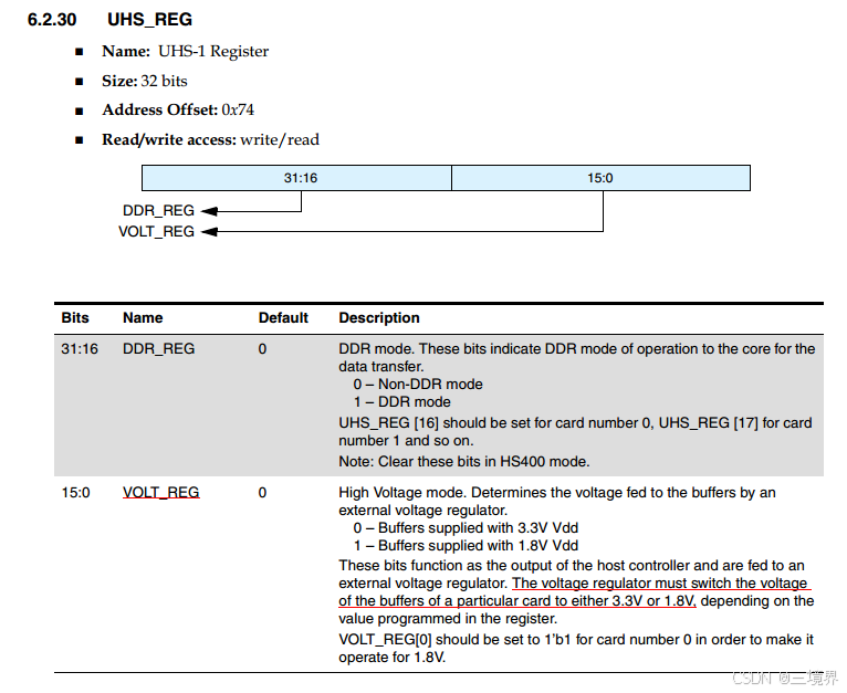
/* * Program the voltage. Note that some instances of dw_mmc may use * the UHS_REG for this. For other instances (like exynos) the UHS_REG * does no harm but you need to set the regulator directly. Try both. */ uhs = mci_readl(host, UHS_REG); if (ios->signal_voltage == MMC_SIGNAL_VOLTAGE_330) uhs &= ~v18; else uhs |= v18;
if (!IS_ERR(mmc->supply.vqmmc)) { ret = mmc_regulator_set_vqmmc(mmc, ios);
if (drv_data && drv_data->switch_voltage) return drv_data->switch_voltage(mmc, ios);
下面是这么一段注释:
1 2 3 4 5
/* * Program the voltage. Note that some instances of dw_mmc may use * the UHS_REG for this. For other instances (like exynos) the UHS_REG * does no harm but you need to set the regulator directly. Try both. */
/** * mmc_regulator_set_vqmmc - Set VQMMC as per the ios * * For 3.3V signaling, we try to match VQMMC to VMMC as closely as possible. * That will match the behavior of old boards where VQMMC and VMMC were supplied * by the same supply. The Bus Operating conditions for 3.3V signaling in the * SD card spec also define VQMMC in terms of VMMC. * If this is not possible we'll try the full 2.7-3.6V of the spec. * * For 1.2V and 1.8V signaling we'll try to get as close as possible to the * requested voltage. This is definitely a good idea for UHS where there's a * separate regulator on the card that's trying to make 1.8V and it's best if * we match. * * This function is expected to be used by a controller's * start_signal_voltage_switch() function. */ intmmc_regulator_set_vqmmc(struct mmc_host *mmc, struct mmc_ios *ios) { structdevice *dev = mmc_dev(mmc); int ret, volt, min_uV, max_uV;
/* If no vqmmc supply then we can't change the voltage */ if (IS_ERR(mmc->supply.vqmmc)) return -EINVAL;
switch (ios->signal_voltage) { case MMC_SIGNAL_VOLTAGE_120: return mmc_regulator_set_voltage_if_supported(mmc->supply.vqmmc, 1100000, 1200000, 1300000); case MMC_SIGNAL_VOLTAGE_180: return mmc_regulator_set_voltage_if_supported(mmc->supply.vqmmc, 1700000, 1800000, 1950000); case MMC_SIGNAL_VOLTAGE_330: ret = mmc_ocrbitnum_to_vdd(mmc->ios.vdd, &volt, &max_uV); if (ret < 0) return ret;
dev_dbg(dev, "%s: found vmmc voltage range of %d-%duV\n", __func__, volt, max_uV);
/* * Due to a limitation in the current implementation of * regulator_set_voltage_triplet() which is taking the lowest * voltage possible if below the target, search for a suitable * voltage in two steps and try to stay close to vmmc * with a 0.3V tolerance at first. */ if (!mmc_regulator_set_voltage_if_supported(mmc->supply.vqmmc, min_uV, volt, max_uV)) return0;
staticintmmc_regulator_set_voltage_if_supported(struct regulator *regulator, int min_uV, int target_uV, int max_uV) { /* * Check if supported first to avoid errors since we may try several * signal levels during power up and don't want to show errors. */ if (!regulator_is_supported_voltage(regulator, min_uV, max_uV)) return -EINVAL;
/* * The card should drive cmd and dat[0:3] low immediately * after the response of cmd11, but wait 1 ms to be sure */ mmc_delay(1); if (host->ops->card_busy && !host->ops->card_busy(host)) { err = -EAGAIN; goto power_cycle; } /*
card应当立即驱动cmd和dat[0:3]到低电平,在cmd11响应之后,这里等待一秒做确保
1
2
3
4
5
6
7
8
9
10
11
12
13
14
15
16
/*
 * During a signal voltage level switch, the clock must be gated
 * for 5 ms according to the SD spec
 */
clock = host->ios.clock;
host->ios.clock = 0;
mmc_set_ios(host);

if (mmc_set_signal_voltage(host, MMC_SIGNAL_VOLTAGE_180)) {
	/*
	 * Voltages may not have been switched, but we've already
	 * sent CMD11, so a power cycle is required anyway
	 */
	err = -EAGAIN;
	goto power_cycle;
}